
SPI
Official instructions
http://www.raspberrypi.org/documentation/hardware/raspberrypi/spi/README.md
This seems to work ok now but if you have problems have a look at this thread
http://www.raspberrypi.org/forums/viewtopic.php?f=28&t=97314&sid=863f988277798afff9076f1a7b7f7822
Basic setup for MAX7219
- For 8×8 display Connect hardware as per info in README file
- Make sure SPI is enabled – from Raspi-config tool
- Make are Python dev and pip are installed
sudo apt-get install python-dev python-pip
- Install SPIdev
sudo pip install spidev
- Download the library from github
git clone https://github.com/rm-hull/max7219.git
- Install it, make sure you are in the same max7219 directory when you do this
sudo python setup.py install
- Probably best to restart everything for good measure
- Check the test application works ok – does not need sudo with Jesse
sudo python max7219/examples/test.py
- I found the test prog ran too quickly to really see, so changed a number of the timings
basic setup for DS18B20 temp sensors
- sudo modprobe w1–gpio
- sudo modprobe w1–therm
if these modprobe does not work try this
sudo nano /etc/modules
and manually add the following 2 lines, but to confuse things with a Pi 2 you don’t need these ….
w1-gpio
w1-therm
you might also need
# device tree config
dtoverlay=w1-gpio,gpiopin=4
I have also found with A+ pi’s and NOOBS 1.4, SPI to work only by disabling device tree – make sure you have the following line in /boot/config.txt [ to edit sudo nano /boot/config.txt]. That said the Pi 2 would only work without disabling device tree ……
device_tree=
while you are in config.txt check the following line is there
dtparam=spi=on
To check it actually working try
- cd /sys/bus/w1/devices
- ls
- cd 28–xxxx (change this to match what serial number pops up)
- cat w1_slave
Ref the following page for source info on this
https://learn.adafruit.com/adafruits-raspberry-pi-lesson-11-ds18b20-temperature-sensing/ds18b20
i2c
There is a good set of instructions on the Adfruit website
https://learn.adafruit.com/adafruits-raspberry-pi-lesson-4-gpio-setup/configuring-i2c
Also with newer kernel you should just have to select I2C using the configuration tool
alternatively to do it manually …. – this is also a good way to check all it well
To set-up an Rpi to use it’s i2c port you first need to complete the following set-up actions The first thing is to edit the modules file using :
sudo nano /etc/modules
and add the following two lines :
i2c-bcm2708
i2c-dev
Save the file and exit
Lastly you need to edit the modules blacklist file –
[late 2015 update – you do not seem to have to do this now]
sudo nano /etc/modprobe.d/raspi-blacklist.conf
and put a # symbol at the beginning of the two lines so that they look like this :
#blacklist spi-bcm2708
#blacklist i2c-bcm2708
Save the file and exit, then re-boot
There are a number of test commands which are useful for basic testing, to install these
sudo apt-get install python-smbus i2c-tools
Basic tool commands
i2cdetect i2cbus  # probs the i2c bus to see what is connected
                  # for a device set to add 00 you find is
                  # connected at address 20hex
i2cset  i2cbus chip-address data-address value
                  # write value to to data address
i2cdump i2cbus address    # read all device registers
i2cbus, depends on what sort of Rpi board you have – 0 for a rev 1, 1 for rev 2
chip-address, hardware address of connected i2c device – 20h by default
data-address, internal i2c device register to be addressed [0-7fh]
value, the value [0-ffh] you want to place in the register pointed to by data-address
Use sudo i2cdetect -y 0 at the command line for a quick check to see if the bus is working. You should see ID #68 show up – that’s the address of the DS1307! If you have a rev 2 Pi, you will have to run sudo i2cdetect -y 1 as the I2C bus address changed from 0 to 1
examples for MCP23017
i2cset 0 0x20 0x00 0x00  # setup portA as all outs on a rev1 rpi

i2cset 0 0x20 0x14 0x55  # write 55h to portA on rev 1 rpi
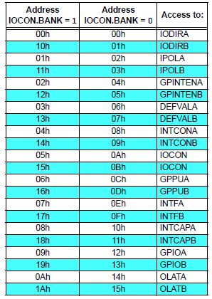
MCP23017 register listing
http://www.lm-sensors.org/wiki/man/i2cdetect
http://www.lm-sensors.org/wiki/man/i2cset
http://www.lm-sensors.org/wiki/man/i2cdump
DS1307 setup
look at Adafruit examples- make sure you read them carefully as there are some typo corrections in the text
https://learn.adafruit.com/adding-a-real-time-clock-to-raspberry-pi/wiring-the-rtc
based on info from
https://pihw.wordpress.com/2013/04/08/three-fun-things-to-try-with-your-raspberry-pi-off-the-shelf/
The batch file example does not seem to work but this did
#!/bin/bash
echo "PCF8591P ADC and DAC Test Program"
echo "================================="
echo "Simple test program to demo the PCF8591P"
echo "Connected to I2C bus"

i2c_chan=1
i2c_adc=0x48
adc_channel=1

i2cset -y $i2c_chan $i2c_adc $adc_channel
while true
 do
 i2cget -y $i2c_chan $i2c_adc
 sleep 1
 done
#End
Remember you will need to do a modprobe -x to make is executable
