Retro Elektor Z80 Computer Complete… ?

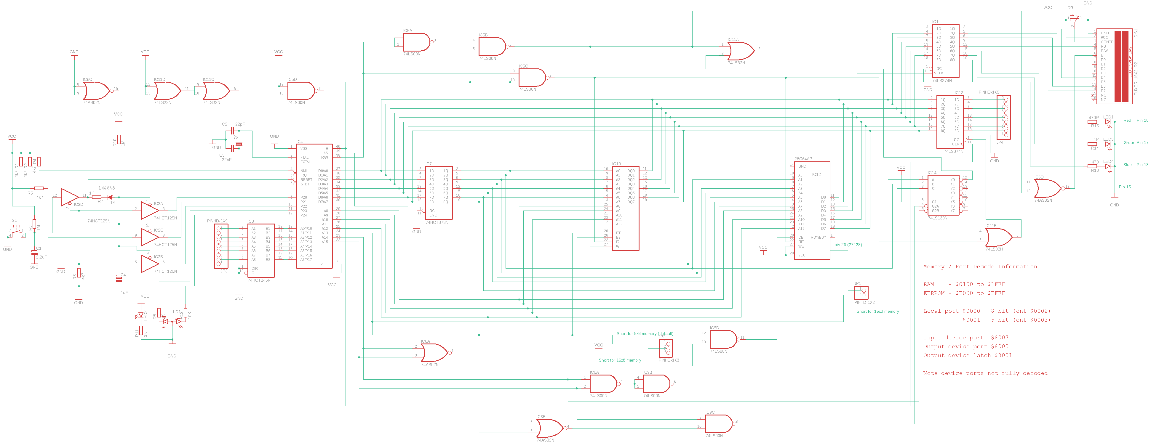
It’s been a while since I posted anything on my Z80 project so thought, having got to the point where it is ‘finished’ last week now would be a good time for an update. The forward plan at the time of the last bog post had been to look at adding more memory to allow me to run the MS BASIC variant originally supplied with the NASCOM 2 computer. Initially I designed a simple add on memory board with 3 sockets for either 8K RAM or EPROMs, with the relevant decode logic. This developed a little, largely down to availability of suitable RAM chips to a single 32×8 RAM and a 8K EEPROM (I treat these as EPROMS -i.e. no onboard programming capability). rather than wire this myself I went down the route of a simple PCB. As you can see in the picture a bit further down the blog I opted for a half size PCB. The simple reason for this is that I run the free version of Eagle and this was the biggest PCB it will let me layout !

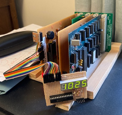
With a 3+ week turnaround for the PCB I was wondering what other feature I could usefully add and landed on including a real time clock capability. Existing RTC addon’s for Z80 boards seemed to use use I2C modules, but not wanting to implement I2C I opted for a older EPSON RTC the 72421, that I could tie directly in to Z80 IO ports. I could have gone down the route of using a RAM chip module with a build in RTC and battery but this would have meant memory mapping the clock IO which is a bit of waist given separate IO space is key Z80 feature over say a 6502. The 72421 is relativity easy to implement. The only real complexity was sorting out the battery back-up. Newer RTC’s provide a bit more help here but are much harder to find in old school dual in line packages. In the end I opted for a super capacitor over a rechargeable battery. The back-up time is only about 24 hours – still more than enough for this application. The picture on the left shows the completed RTC board, with a bit of room for maybe something else in the future. I have extended the monitor s/w to include routines to read the clock, which because of the all the text involved ended up taking most of spare room in the 2K address space.

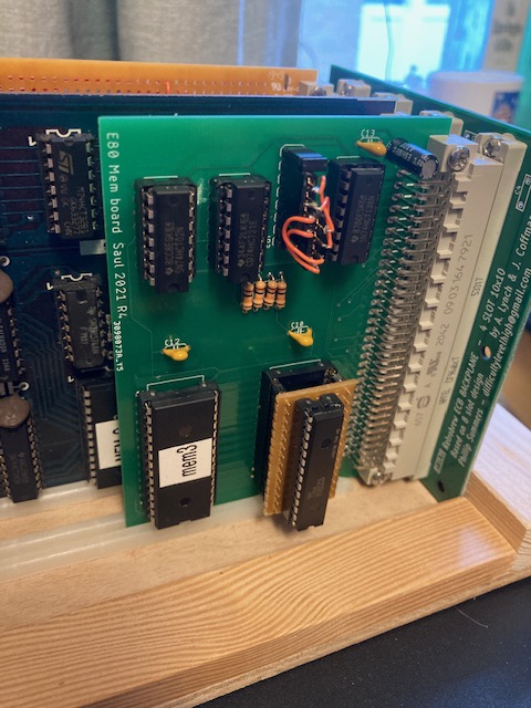
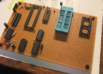
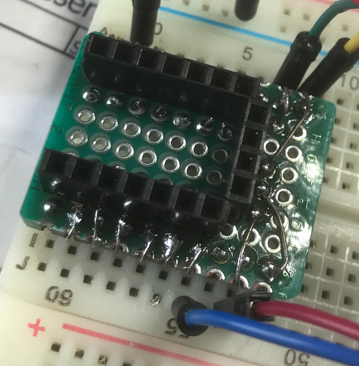
With the memory PCB due I got around to ordering the memory chips, as you can see from the picture on the right I showed my age by missing that a lot of 28 pin devices are in a narrow format these days, hence the adaptor ! Functionally the board worked first time, there were a few bits I would change but nothing to drive a new pcb order. With the board working I now had around 30K of usable RAM, 2K monitor space and 8K (or16K) read only memory at the top of the 64K map.

One interesting side note, in my earlier post I expressed a concern about a loose memory socket causing reliability problems on the processor board. This got to the point where it was really annoying me, but looking at the problem I realised it only failed when I powered down the board – i.e. it was not directly related to the socket. So digging around with a scope I realised the reset time was all off, two replacement tantalum capacitors later and I have not had any more problems.

To get BASIC working I needed to make few modifications to my monitor program to provide the hooks for terminal calls used by BASIC. It was a pleasant surprise that all this worked first time so I was back using NASCOM basic for the first time since around 1990 when I last turned on my NASCOM 2.

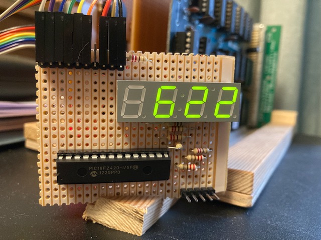
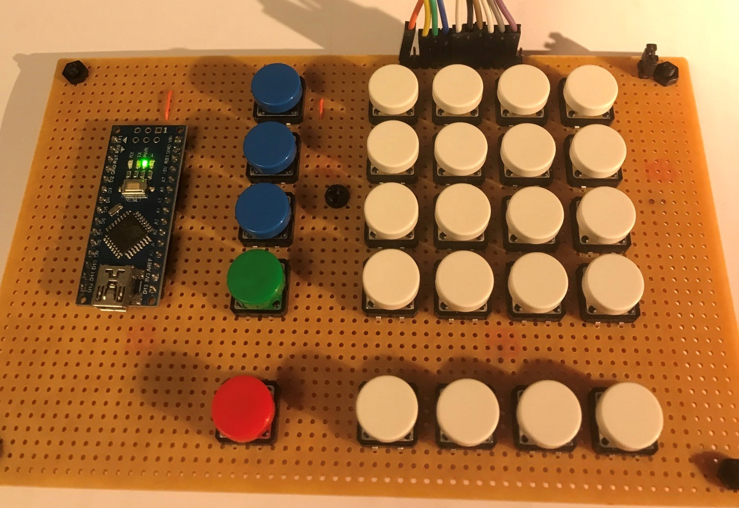
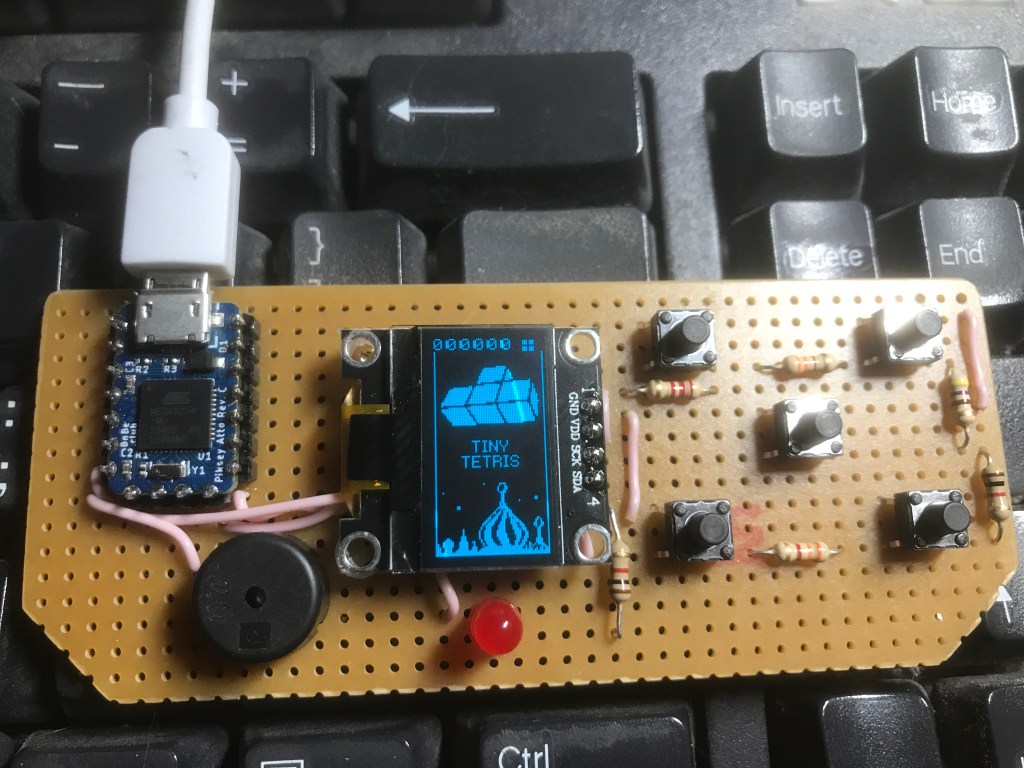
One of the reasons for adding the RTC was so the computer could sit on my work desk as a slightly over sized clock. The plan at the time was to use some sort of retro display type to compliment the age to the Z80 board. The trouble with this is that it would tie the processor up with driving a multiplex display not leaving much time it to do anything else. Coincidentally around this time I had an idea for another project which will need me to move data directly from a Z80 bus to a PIC. As a proof of concept for this I pulled together a simple 4 digit LED display driven from and 18F series PIC. Initially this is being driven via the a Z80 PIO port, the next stage will be to change it to connect directly to the processor data bus.

As currently configured every minute the RTC creates a Z80 interrupt which sets off an update of each clock digit to via the PIO. The PIC drives the multiplex display as a background routine with each PIO update causing a PIC interrupt to refresh the clock digit data. The net result is there is almost no additional load on the Z80 and I have a clock on my desk.

Where to from here?

Getting the retro Z80 board working and developing it has be great fun but in truth it is in not the best test test bed for the PIC interface I am designing. So for this I am building a R2014 ‘clone’ Z80 CPU board, more of this in the future. I will come back the Elektor computer to look at adding a the VDU card I mentioned in my last post, but I suspect this will end up being a Christmas project.

Posted in Uncategorized | Tagged , | Leave a comment

Bringing a 39 year old Elektor Z80 Computer to life

With my retro 6303 board finished I decided to look at an old Z80 board I found in the attic awhile ago. The board design design in question was published in the May 1982 issue of the Elektor magazine. I had originally planned to use it as part of a theatre lighting controller, but ended going down another route.

The board is literally just CPU, buffering and memory, designed to work with the ‘Elektor 80Bus’. Having just a halt LED for feedback testing was a challenge, but when a single halt instruction at location 0000h did not work, clearly there was something not right. Setting up a simple loop I was able to find a track fault on one of the address lines. Once I had fixed that the board sprung into life.

Clearly to do much I was going to need a bit of IO so designed a relatively simple parallel and serial interface board using a Z80 PIO and 8251A, wiring it manually to cut out the PCB fabrication time loop. This worked with few problems, in the main this was down to following the same route as the 6303 board to ‘buzz-out’ and test each sub-element as I built it, rather than go for a ‘big bang’ approach.

With some real-world IO available I started to think about a monitor program, one initial thought was to use the NAS-SYS as I have an existing NASCOM 2 and eventually want to get NASCOM basic running on it.

I had ensured the IO addressing matched that used in the NASCOM, but as there was a lot more complexity than I needed in NAS-SYS so I decided against using it. Still rather than resort to starting from scratch I looked around to see if there was another existing simpler monitor I could re-purpose. There are number of options focussed on implementing CP/M which I was not interested in but after bit of searching I found one on the Glitch Works website. Other than it’s simplicity it is also written with a very modular serial interface avoiding the need to fiddle with main code when you change UART type. As luck would have it someone had already written a set of routines for the 8251a ! The monitor is very simple – around 300 bytes & just 6 commands, but everything I needed.

D – Display memory xxxx to yyyy
E – Enter Data at yyyy
L – Load Hex 8 data
G – Run Code at xxxx
L – Load Hex 8 data
O – Output to Port xx data yy
I – Fetch data from Port xx

Written in 8080 assembly code it ran first time on the Z80 board which was good. That said having used it for a few days I felt the need to add a some ‘home comforts’ and not wanting (or needing) to learn 8080 assembler mnemonics spent a bit of time converting the code to Z80 assembler. Once this was debugged I added the following;

  • Validation to trap invalid hex characters and allow you to escape from commands more cleanly
  • The H command to display command options
  • The T command to make development of new commands without re-programming the monitor EEPROM easier

The T command was to address a concern I have over the CPU EPROM socket which feels quite loose, so I am trying to avoid inserting / removing the chip too often !

I also spent quite a lot of time looking at the HEX8 download code before coming the realisation that the problem was with my HEX8 files not the monitor code ……

In parallel with coding I sourced a simple backplane, initially I tried to use a VME backplane but there was no easy way to sort out the functionality clashes between to the 2 buses. Again hunting around the internet I found a retro Z80 computer group in the US with lots of useful stuff and most importantly Gerbers for a simple 4 way backplane, another problem solved.

Looking forward my ‘to-do, list includes;

  • A simple memory board, nothing complicated just 3 or 4, 8K RAM/ROM sockets
  • The memory board will hopefully allow me to allow me to implement a modified version of NASCOM BASIC
  • A video card, Elektor published a video card design to work with this CPU board, the PCB is no longer but again through another Retro Z80 group this time on FB someone got in touch to say he had re-laid it and had a spare PCB so that will be a bit of a project later in the year I hope

All development stuff and schematics etc, can be found on my GitHub site [ note this is still work in progress ! ]

Posted in Uncategorized | Tagged , | Leave a comment

Retro63 Update

I thought it was time for an update on the progress of my 6303 computer build, now officially named Retro63. To complete the build I have added a keyboard. I looked around at the readymade options but decided to go DIY for the moment. To keep things simple I used a Arduino Nano to scan the matrix of keys (there is an existing library to use for this). The 6303 is simply presented with 7bit ascii and a data available flag. Initially I am scanning for the keypress flag but can easily change over to have it create an interrupt each time a key is pressed.

To keep things together I build a simple wooden frame for the keyboard and processor board to sit in. The only other hardware change is the addition of a simple buzzer driven from a processor port.

With the keyboard working my focus changed to getting a basic monitor program up and running. You can see this booting in the following video.

The monitor functions are:-

  • display memory
  • modify current memory address
  • move one address forward or backwards
  • jump to memory address
  • execute program at current memory address
  • basic search

There are also quite a lot of sub-routines to make doing ‘stuff’ easier.

The next iteration of the monitor will include the ability to load and save via the serial port but I’m not planning a lot beyond that – I may well in time implement one of the existing monitors others have written but that is a way off currently.

I have been a little distracted by the arrival of the new Pi Pico for the last couple of days, thinking about how I can usefully use one on the Retro63 project !

Posted in Uncategorized | Tagged | Leave a comment

6800 (6303) Christmas Project

I decided to step up a complexity level for my Christmas project this year and have a go at building a Retro Computer. Initially I was going to do something based around the 1802 processor but as I already have one of these running I thought to try something a bit different. Having grown up very much as a Z80 person I have never done much with 6800 series processors so decided now was a good a time as any to rectify this omission! After a bit of looking around I landed on the 6303 from Hitachi, this is essentially a Motorola 6803. This has an extended 6800 compatible command set with a bit of RAM and peripheral IO all on a single chip. The 6303 is also a lot easier to source and work with than the original 6800 making it a good choice. Addionally I had found a couple of examples of other 6303 DIY computers online which helped a lot in terms of filling the gaps in the official documentation.

To avoid creeping features, for once I spent a bit of time thinking about what I wanted the computer to do and more importantly what it didn’t need to do. For instance I wanted to interface some form of keypad and display, but did not need much additional IO beyond that. The same with memory 8K RAM & 8K EPROM would be fine, no need to cater for further expansion. the 6303 includes a basic serial interface so no need to include a separate UART chip. initially I was going to include a separate 6 digit display but swapped to the 16×2 line LCD you can see in the finished computer when I realized I could just fit it on the board, with the interface logic underneath.

Specification

  • Processor – 6303 clocking @ 1.2288MHz (4.9152MHz external crystal divided by four)
  • RAM – 8K (0000-2FFF)
  • EPROM 8K (E000 – FFFF), 16K selectable via onboard links
  • Ports
    • On CPU 1x5bit 1x8bit (inc a serial port)
    • External 1 x 8 bit input (for keyboard interface)
    • External 1 x 8 bit output, connected to LCD
  • Power 5V at less than 100mA

To make initial code development a easier i’m using a 28C64 EEPROM rather than a traditional ERPOM. This has greatly reduced test cycle time over using an EPROM!

In terms of the physical build I decided early on to use strip board,

initially I was looking to use a Vero wiring pen to make the interconnections but in the end opted for more tradition link wires all be it with PTFE insulated cable. This does not melt if you accidently catch it with the soldering iron making things a lot easier when as the wiring gets more congested.

Given I was building this over Christmas when getting replacements is hard I was very focused on not accidently damaging any ICs through wiring errors, to this end unusually for me I was very disciplined in checking for continuity and shorts before plugging anything in! This combined with proving out bits as I finished them meant I was relatively confident of the existing build each time I wired in new a element. The only real problem I had was with the LCD display which turned out to be a faulty display rather than an error on my part – I ended up stripping it out and wiring up to a Arduino to confirm this. It is also fair to say having a good digital scope was a big help, particularly getting the reset timing sorted out (mode selection on 6303 takes place as part of the reset sequence so getting the timing right is important).

I have been using an online assembler called asm80 to write test software, this is a great tool supporting development of a number of 8bit processors including an IDE and emulator. At some stage I do need to move on a different assembler as asm80 does have a few eccentricities in terms how it emulates 6800 code (in fairness it was originally written for the Z80) and does not support the extended 6801 codes available on the 6303. That said asm80 is very easy to use so I will stick with it for now.

The next stage is to sort out a basic keypad, most likely based around an Arduino or PIC, to avoid putting the scanning overhead on the 6303. After that I want to develop / adapt a simple monitor program, mainly this will act as a bootstrap to facilitate loading software via the built in serial port. Finally once I have firmed up on the size of the keypad, clearly some form of enclosure is needed – something custom made in wood I suspect.

Schematic

Credits

Daniel’s bits, bytes & pieces , this was a really useful block documenting Daniel’s build of a 6303 based computer, first got me looking at a 6303 as the processor choice

asm80 support a number of 8 bit processors providing assembler, IDE and emulator

How to strip PTFE wire – the clue to use heatshrink tube on a pair of pliers was a game changer

Other links that I have found useful will be added in time a dedicated 6800 section of the blog

Posted in Uncategorized | Tagged , , | Leave a comment

Piksey Atto

I was recently sent a Piksey Atto by it’s creators at BnBe club. The Atto is the Latest in their range of small Arduino IDE compatible micro-controllers. You can see the earlier Piksey Pico in my last post on the binary clock. The Atto is a real step down in size from the Pico measuring just 20 x 13mm. While there are other very small Arduino compatible micro-controllers they are often limited by choice of processor and / or connections. With the Atto the makers have opted to use the same processor as the Arduino Leonardo (ATmega32U4) this ensures good level of capability and importantly simple installation – no additional config or 3rd party drivers needed just select the Leonardo in the IDE.

To get as much IO as possible 3 sides are used for connections. The Atto has castellation holes making it flexible to use both on prototyping boards and PCBs.

To make access to the end connections a little simpler I made a small adapter board from bits I had to hand.

Communication with the Arduino IDE was as promised very straight forward and I had the usual blink example working without a problem – note, the Atto does not have an onboard LED so you have to connect to your own to see Blink working.

Next was to decide an application for the Atto. IOT applications are an obvious route given it’s size but I had recently seen Arduino Nano code for a mini Tetris game and so for a bit of fun thought this would show off the size of the Atto well and be a bit different. You can see the finished results below and the to the right.

I had to make a couple of changes to IO assignments in the s/w as the Leonardo uses different pins for I2C to the Nano, the only other job was ‘tuning’ the buttons. The Tetris game connects to the buttons via a single analog pin using dividing resistors to give a different analog reading for each key combination. I had not seen this before and although not strictly needed here is simple way to squeeze a bit more IO out when you are short. For more on this see the following link http://fritzing.org/projects/arduino-5-buttons-keypad .

All in all the Atto is useful addition to the range of Arduino compatible micro-controllers, for me using the Leonardo processor is great step up from the competition, taking away the need for extra 3rd party drivers. It’s size does mean a couple of compromises, no onboard power regulator (there is still an external 5V connection pin) and no LED but I am happy to take these given it’s small size.

Credit to Badfeed for the original Tetris code

Posted in Uncategorized | Tagged , , | Leave a comment

Lock Down Clocks

I seem to have got a little fixated on clocks over the last couple of months, but rather than go down a simple route I have tried to use parts I already had ‘in-stock’. For example this picture is of a binary clocking using some phosphor neon’s I had in a draw rather than led’s to indicated the time, but more of that later in the post.

My first lockdown clock build on the face of it is just a simple digital clock but rather than use a display with the driver built in I got the 8266 to do everything. Then to really mess things up I used a 8266 with not quite enough IO so added PIC programmed to act like a 2 to 4 line decoder for the digit selection. Then as the analog input line was still spare I added auto brightness control. The 8266 connects to the internet once a day to correct any time drift. The only cheat is the flashing colon, with no IO to left this it’s driven from a simple 2 transistor flip-flop.

Next back to green phosphor neon’s, I was having a bit of play with them to understand potential driver circuits for a nixie clock I am planning when I had the idea they would make a good indicators for a binary clock … This would also be an opportunity develop the clock elements for the planned nixie clock as the nixie tubes themselves were still on their way from Eastern Europe !

Again looking around for bits I had immediately available I landed on developing a ‘re-usable’ clock source design using an ESP01, building on the s/w I had used for the earlier digital clock. This outputs the ‘time’ once a second via the ESP01’s serial port as a simple text string. A bit of added complexity was to correct for summertime, again it is updated from an a NPT server once a day or manually via a push button. The serial time feed is read into a second micro-controller that sorts out the binary display. For this I used a Piksey Pico Arduino compatible uP that I had got a while before from a Kickstarter. These have the advantage of being smaller than a Nano but still have slightly more accessible IO.

In the process of testing the clock I did mange to destroy an ESP01 – they really do not run for long on 12V and one Piksey ( a lose wire touched the 115Vdc rail !), but you can see the finished results below. I think the indicators are a really pleasing green much more subtle that using these newfangled led things….

The video shows the start up sequence with the uppermost orange neon flashing until the wifi connects then you see the whole display update as the Piksey starts to get updates from the ESP.

The next plan is to put it in some form of display case to avoid accidental electric shocks !

Posted in Uncategorized | Tagged , , | Leave a comment

Pi Xmas Tree Forest Complete

Looking around I realized I have collected quite a lot of Pi Xmas trees over the years. Clearly setting them up individually would take quite a lot of Pi’s, but could I get them all working from a single Pi ?

It was immediately apparent some sort of fiddling would be needed as the Pi 3d tree on it’s own uses all the available IO !

Accepting this would be viewed from the front I was able to save a number of IO lines by ignoring the leds on the back of the 3d tree. This still left me short by about 8 lines so I added an MCP23017 I2C port expander to give to make up the difference.

As you can see the result is not pretty but it works, albeit with a little blue-tack and packing tape holding things together.


This was also an opportunity to use the RasPiO Breaboard Pi Bridge, with all the IO broken out in numerical order this really helped me keep my sanity.


Anyway happy Christmas from MeanderingPi

Posted in Uncategorized | Leave a comment

GPIO Xmas Tree 2019 – Pimped

Having seen Andrew was launching a new tree this Christmas with the added twist of a bit of surface mount soldering I thought, yes this is a must for the 2019 decorations.

Then I thought this is calling out for a bit of Raspberry Pi pimping.

As supplied all the led’s as connected in parallel with a simple on off switch / battery. First I isolated the track connections then connected them to individual GPIO lines on a PiZero, which I mounted with couple of stand-offs on the back of the PCB frame.

Next is was just down to a bit of Python. After some experimenting I arrived at a pleasing random flicking effect. The trick here is that slow fades do not work because the PWM routines in Gpiozero are all software controlled so you get annoying flashes when Linux decides to go off and do something else.

The initial consumer review was nice but, there was a compliant that the flicking could get annoying so I re-purposed the on-off switch to select between flicking and static in s/w. Finally I added a further push to allow the Pi to be shutdown cleanly.

The s/w can be downloaded from my github – it is not thing of beauty but it works !

How the kit arrives

Posted in Uncategorized | Leave a comment

Pi Test-bed Upgraded to fan Cooled Pi4

image-6.jpg
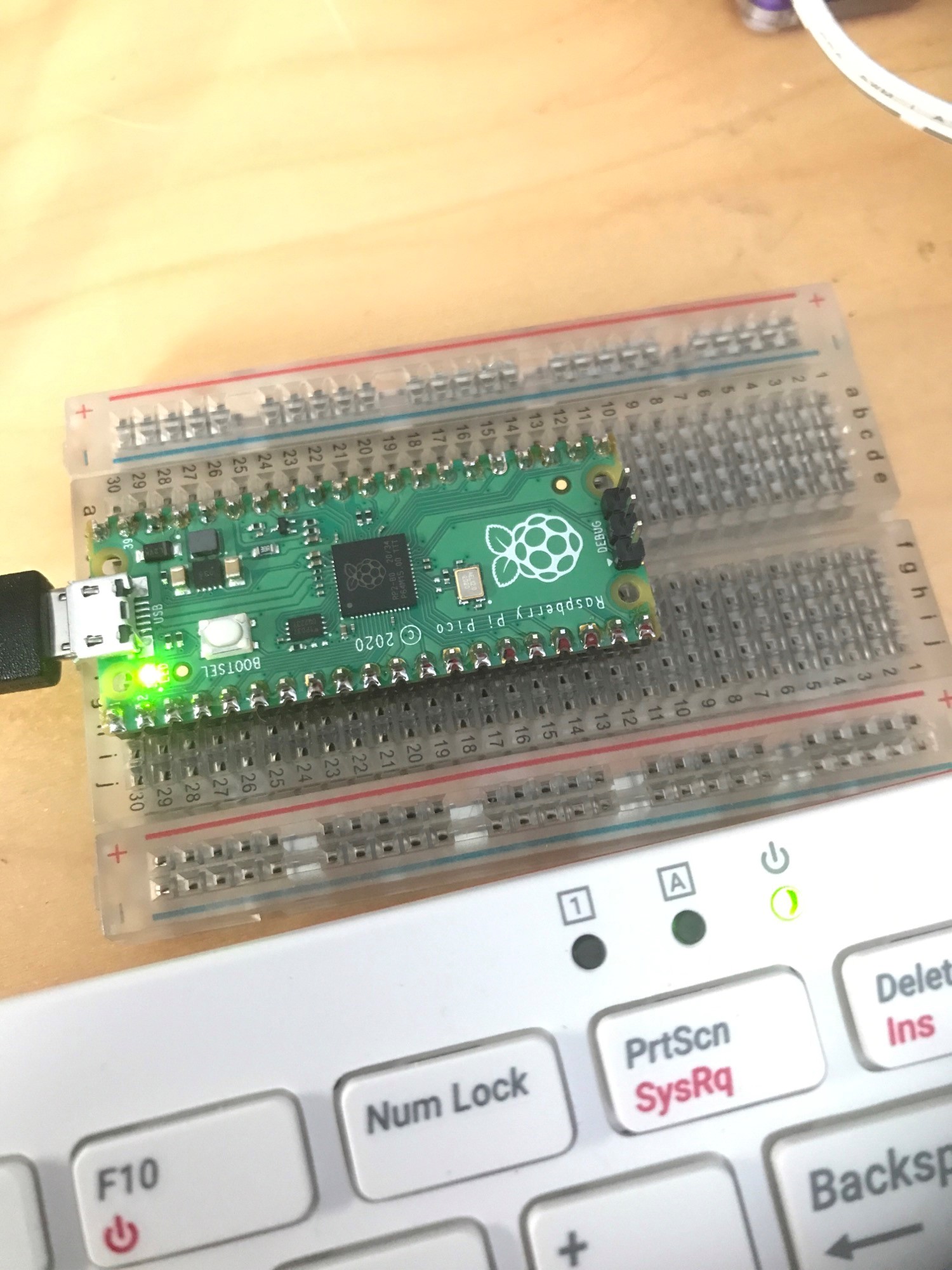
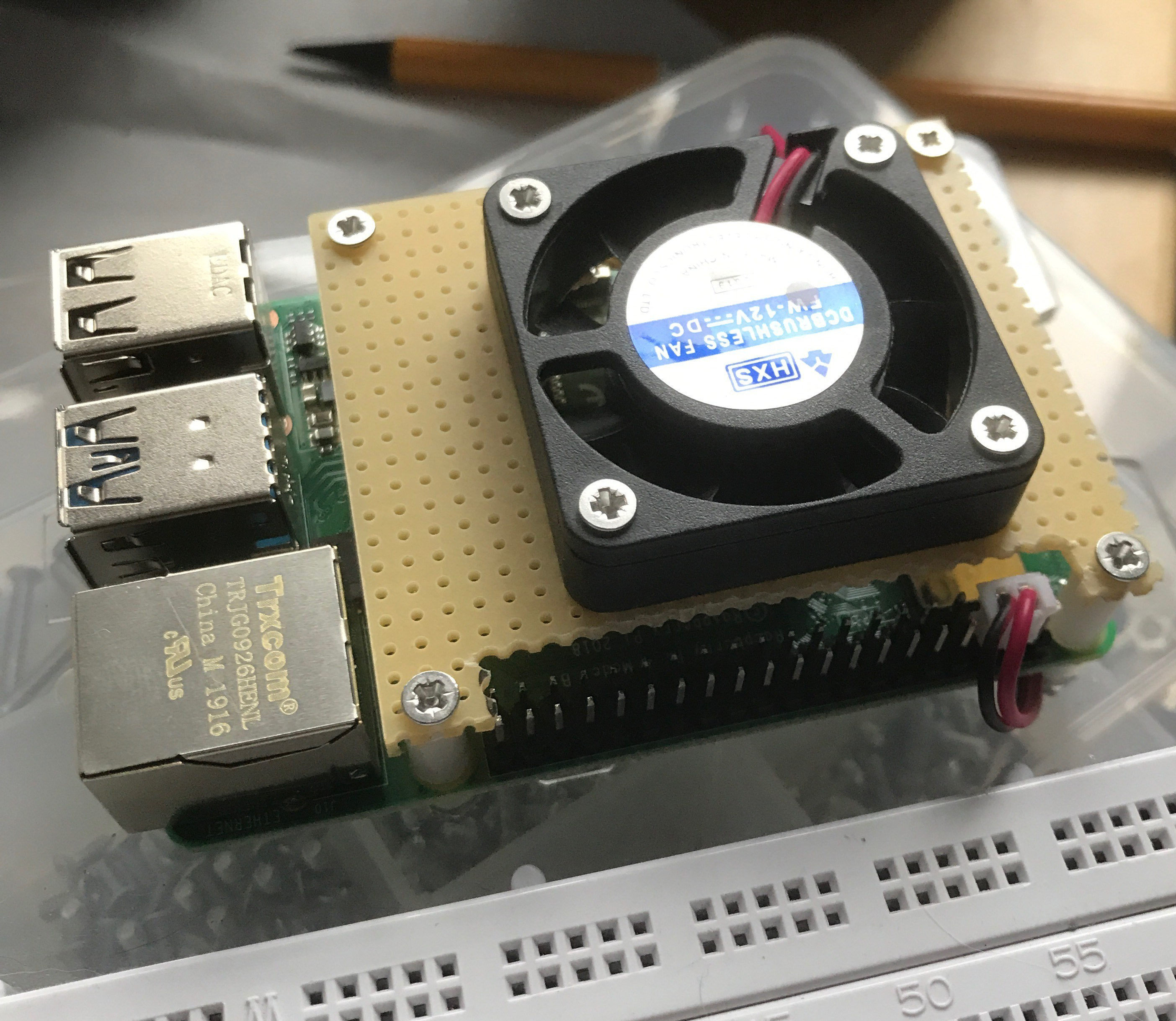
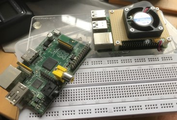
My Pi test-bed dates back to the first Pi I got 2012, upgraded with each new release of h/w. Other than the Pi the only other change in that time has to modify the mounting when Pi’s with mounting holes first arrived on the scene !

The room I work in gets very hot in summer so with all the discussions around how hot the new Pi4 gets I decided to add a DIY fan ‘hat’. I probably should have made this on the 3d printer but as I had some plain prototyping board to hand it seemed a good idea to show how a very cheap ‘no complicated tools needed solution’ could be made.

I started by cutting out a 65mm x 55mm rectangle of prototype board, using the Pi as a image-4.jpgtemplate I then marked out and drilled (with a 3mm bit) the 4 corner holes.

The fan I used came from ebay, it is a 12v 40mm PC fan costing about £2.50. Here I am running it from 5 volts, while this means it will run slowly it does have the advantage is that is effectively noiseless.

Next I marked out the positions of the fan mounts a main cut out. Lastly using the Pi as a template again marked out the cutout for the PI header.

Prototype board can easily crack, to reduce this risk I made sure the cutouts followed the  matrix hole positions and then used a 2mm drill to ‘extend’ extend them. I could have been a bit neater doing this but it worked out ok. Any ridges I carefully filed down with a needle file. The tip here is to make sure you support the board on a flat surface.

Lastly I mounted the fan on the board with four 2mm nuts & bolts. To attach the ‘fan hat’ to the Pi I used 10mm spacers from ‘stock’.Image-5

The fan came with a 2 pin connector that I connected directly to 5V and Gnd on the Pi header.

The fan does not seem to move much air but importantly it ensures a continuous ‘disturbed’ airflow over the main chips on the Pi. With a room ambient of around 25C the Pi processor temp sits at 44-45C (Pi lightly loaded), disconnecting the fan this went up to 65C within a few minutes.

With a bit of extra filing I could improve access to the header pins but as I mainly use this Pi for s/w development my need to access the header is limited.

image-7.jpg


Posted in Uncategorized | Tagged , | Leave a comment

TEC-1 Computer Build Complete


Image-10
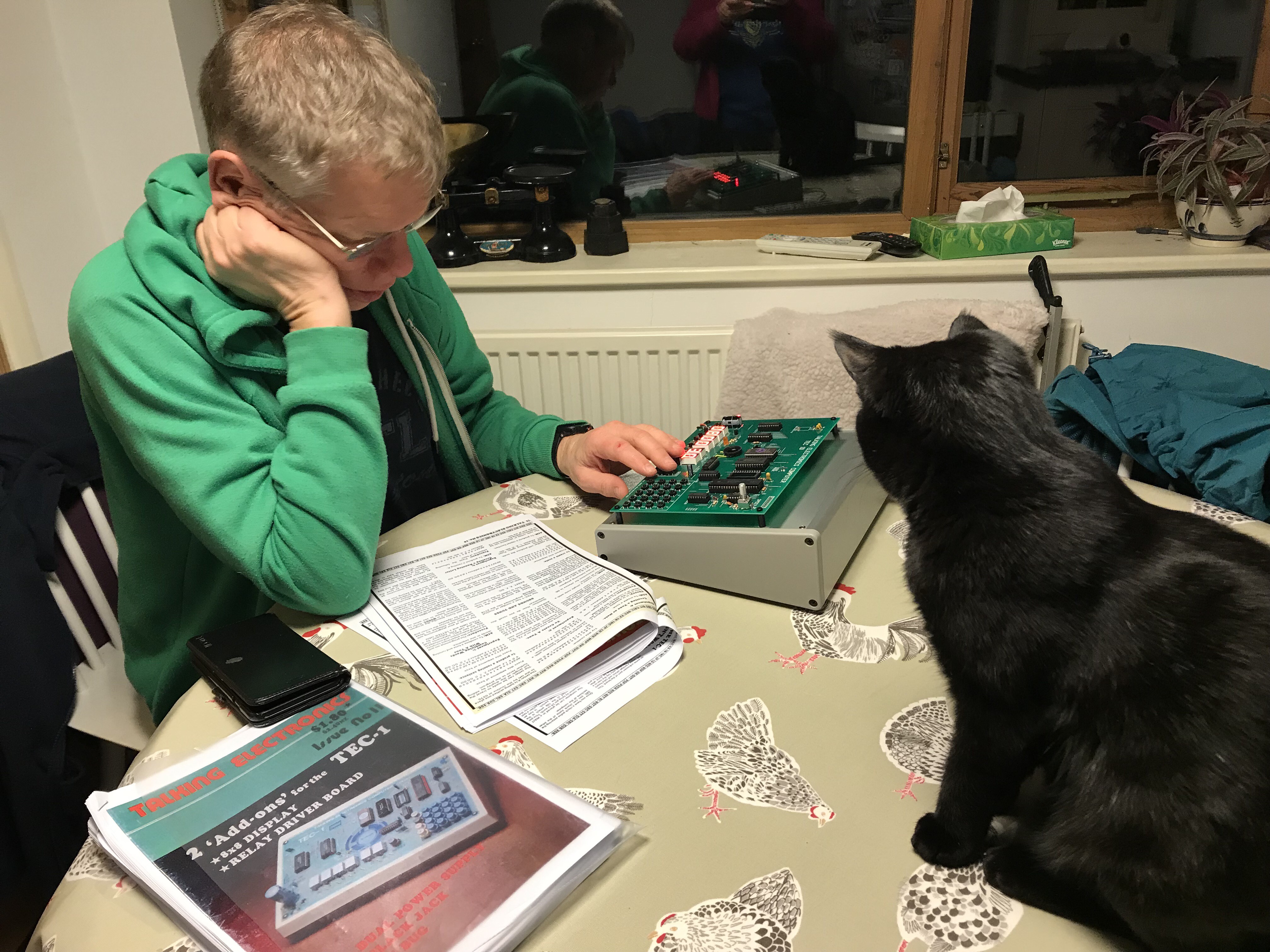
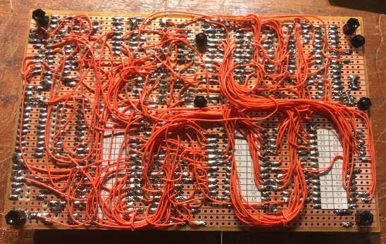
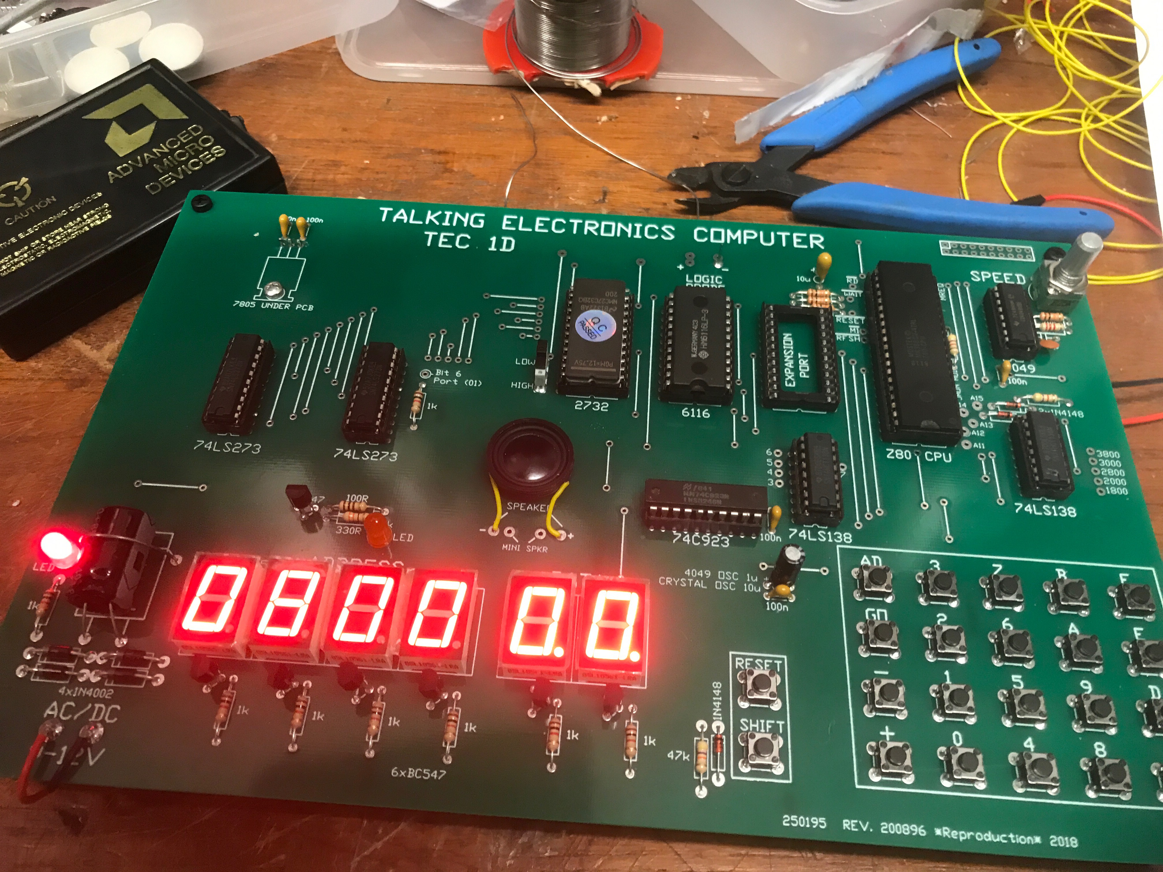
Following a number soldering sessions during the week I finished the TEC-1D build over the weekend. The next stages was to check out the oscillator circuit and the keyboard circuit. The former as there was a warning that not all variants of the chip would work. the latter because I was re-using a chip I initially got about 40 years ago for simple computer I built out of discrete TTL. All was well with both so I inserted the remaining chips and powered up.

This went without a hitch with the monitor program running as expected. Next I mounted the TEC-1 on a slopping enclosure.

From here I spent a happy couple of hours running through  simple code examples from

Image-11

Working boxed TEC-1D

the Talking Electronics Magazine.

Next I started to try a few things out on my own, the main difficultly here is that the information is all spread across 6 issues of the magazine including references to future material that I suspect was never published – the magazine only ran for 15 issues. to complicate things a little more there were at least 3 different monitor programs produced.

So my plan is to try and tees out the strands of information into a single list of functions and calls you can make from the monitor programs. I also need get an EPROM programmer so I can try out the last JMon monitor variant. but that is for the future. For now I am just enjoying playing with my new computer !

Image-12

Boo the cat is very interested in Z80 machine code programming


Posted in Uncategorized | Leave a comment