 Looking at my distributed BBC micro:bit clock I got to thinking, could I make a display screen using a number of micro:bits, using the radio functionality to update the screens ?To see if the basic timing would work I created some very rudimentary code on 4 micro:bits. Initially I tried to use the ‘display.scroll’ function. After much fiddling I did get this to work after a fashion, but in truth it looked rubbish. On the point of giving up I thought I would see what it would look like using the ‘display.show’ function. This produced a much more readable result so I decided
  to go on and develop some ‘proper code’. I had previously looked at with David Whale’s python ‘microbit’ module and this seemed a great way to get the text strings ‘into’ the micro:bit. which solved the problem of how to front end the display. The remaining s/w built used in my distributed micro:bit clock.
Software
The software for the scrolling display has 3 elements;
[the pink x in the names indicates the rev number where I plan to develop the s/w further]
1) The micro:bit display node application [node_scroll_showx.py]
This is a simple python app you need to download on to each of the micro:bits that form the message display. The s/w for each micro:bit is identical. The software listens using using the radio function for any messages addressed to it coming from the gateway micro:bit displaying any valid character using the display.show function. It will keep displaying this until it receives a new valid message. The address of each display node is set the first time the s/w is run (normally this would be directly after download). The micro:bit will display a ‘?’, to show the address needs to be configured. The address is set using button ‘a’ and once correct store it using button ‘b’ – the address is stored in non volatile memory. On subsequent restarts it will be automatically selected, but you can change it by holding down button ‘a’ and resetting the micro:bit.
2) the micro:bit scroll display gateway application [gate_scroll_rx.py]
This is a somewhat more complex python app, performing 4 functions receiving messages from the Pi, creating the scroll effect, segmenting the message and finally transmitting the individual character information to the display node micro:bits.
Information is received from the Pi via a USB connection, this is described further in the RPi gateway application section.
Message format
The basic message format is <type><message>. ‘type’ is either ‘1’ to display a static message or ‘2’ for a scrolling message. So for examples if the gateway micro:bit receives the following message ‘2HELLO WORLD’ you would see ‘HELLO WORLD’ scrolled across the display node micro:bits. This would be repeated until the next message is received.
Static messages are automatically truncated to the number of characters in the display. If you want to see how the scroll process works the best way is to look at the python code but in simple terms I create a shift register in s/w and simply cycle it.
Setting the number of nodes
The gateway micro:bit needs to know how many display nodes it is talking to, this is set the first time the s/w is run (normally this would be directly after download). The gateway micro:bit will display a ‘D’, to show the number of nodes needs to be configured. This is set using button ‘a’ and once correct stored using button ‘b’ – the number is stored in non volatile memory. On subsequent restarts it will be automatically selected, but you and change it by holding down button ‘a’ and resetting the micro:bit.
3) The RPi gateway applications
The gateway application running on the RaspberryPi communicates with the micro:bit gateway via a USB connection, using a python module called ‘microbit’ (thanks to David Whale) for telling me about this – here is a link to his github. To date I have just written a few demo applications using the microbit module. When you first run an application using the microbit module it will take you through a setup process to allow the s/w to identify USB connection name. It will attempt to use this name for future connections. If this fails you will need to go through the identification process again, you may also need to restart the Raspberry Pi. The 4 apps I have currently uploaded on to GitHub are;
- A simple program to display a user inputted string, [gateway1.py]
- A clock demo [gatewaytime_date.py]
- A Tweepy application which will scroll any messages with a specific prefix. [tweepy8a_microbitxx.py]
- A basic GUI that allows you to scroll / show strings or display time in a range of formats [scroll_GUIx.pyw]
The GUI app is my first real attempt to use Tkinter and I am sure I have broken a number of, but it seems to work and was interesting to code
Hardware
One of my goals in developing the scrolling display was to avoid any extra hardware or the need for expensive sockets etc. To get the best effect the node micro:bits need to be mounted in a straight line as close together as possible. The mounting board I used is just a bit of fibre board I had spare. Having worked out the required spacing I drilled a series of 3mm hole, then used 2.5mm stand-offs and screws to mount using just the 0v and 3v ‘holes’. Using 3mm 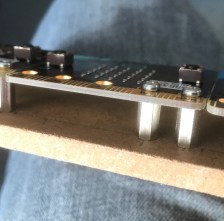 holes with 2.5mm screws gave a bit of ‘slop’ to get everything aligned neatly. You can find a copy of the dimensions I drilled to at the end of this post.
Initially I just used individual batteries to power each micro:bit. Once I was happy the with the mechanical arrangement I found a suitably rated 3.3v supply and changed to power the node micro:bits via the GND and 3v pins – if you go down this route you need to be very careful as an error here could end up destroying all the node micro:bits. Also most importantly you have to include a diode on the 3V line.
This stops a micro:bit ‘back powering’ all the others when you are downloading code to it via the USB line – I am guessing the USB supply on the micro:bit is not rated to drive 10 micro:bits ! You can see how it is wired up in the picture below


Rear wiring detail
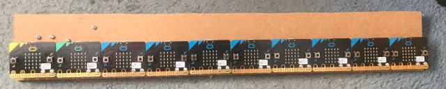
Front face of 10 digit display

The dimensions I used for drilling the mounting board
You can have a look at some short videos of the scroll display working on my YouTube channel
Initial demo
10 digit display demo
Tweet display demo

 Over Christmas while randomly scrolling through my Twitter feed I saw some discussion about the TEC-1 computer. This is a single-board kit dating from the early80s based around the Z80. Instructions on how to build it were published in the computer Australian hobbyist electronics magazine Talking Electronics. The Magazine only ran for 15 issues which is a pity as it had the idea of giving away a blank PCBs for one of the projects featured with every issue and did not have any advertising!


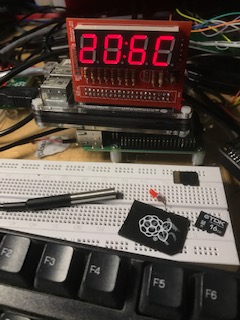 It’s been a good while since I have posted any blog updates, no excuse just distracted by life in general. This is quick weekend project at my daughters request. Concerned that some of the plants in her student flat would struggle in the cooler weather she requested a temperature display. Looking around the options I remembered my first Kickstarter was also set up to display temperature along with time. So a quick hack to remove the time element, change the board mounted DS18B20 sensor to cabled version and add max / min logging and it’s ready to take down to her.
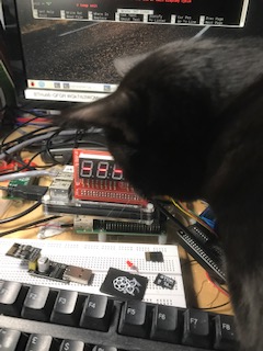


 terminal water damage when the enclosure leaked (to date this is the only Pi of in excess of 30 I have killed). So continuing the hunt I found the news reader Pi I built for my wife based around an article in one of the early Pi magazines. Amazingly it is still working. I plugged it into a monitor just to remember
 what the old LX GUI looked like!
 Just a quick post to say I have updated the TF Wordclock s/w to rev 5, the existing rev 3 s/w was not working reliably with the Nov29 2017 Raspbian update, in truth it had been on borrowed time since early 2017 when there was a major change to the Max7219 library. This did not offer an upgrade path so the TF was stuck with using a depreciated version of the library.
 A couple of weeks ago my wife arrived back from
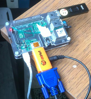
 Once tested this was all packaged in a small box left over from another project. This I was able to mount on to the back of the monitor using one of the VESA mounting points on the back of the screen. The end result looked really quite professional with no unnecessary bits of wire hanging out !
 The idea for this project came from a tweet by David Whale [@whaleygeek] showing a font he had come up with for the micro:bit that managed to squeeze 2 digits on to the 5×5 led display. I have taken initial clock code he wrote and added functionality to read a Real Time Clock module connected via the I2C port together together with some other bits.
 Hardware, it is really up to you, I have used small ‘maker’ interface boards I got made to up allow me to mount the micro:bits vertically on a bit 0.1″ matrix board, but you can easily use one of the commercially available breakout boards. The RTC is a DS3231 RTC module. The only other bit I added was a simple 3.3volt PSU using a 78L33 and microUSB adapter board.

 Always thinking about useful things I could do with a Raspberry Pi my wife asked me about making a time-lapse camera to record some building work at


 I tried a number of different power solutions the simplest being USB battery packs, with a large one I could get about 6 days, but main difficulty I had was that newer ones include a sensing circuit that shut the outputs down if the power drain is below a certain level. So they are fine to run a normal pi 3 but with the zero I found that periodically they would turn off which was not not much use. So going back to the garage I found a car battery, 12V to 5 volt converter and a solar panel from previous ‘projects’. With this combination I have kept the camera powered for over 2 weeks in good weather without a problem. I am doing a bit more work on monitoring the power usage so I can understand how long it is safe to leave the camera for, a bit better – that will be the subject of later blog I hope.
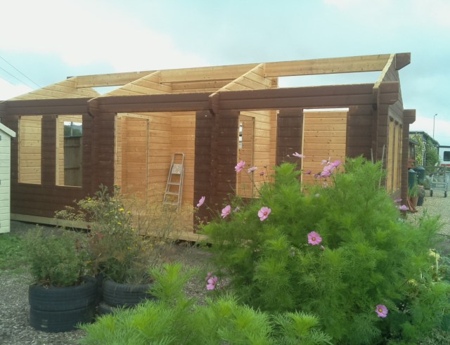
 For the last few days I have been playing with the micro:bits builtin capability to measure analog voltages on P0, P1 & P2 (you can set up some of the other IO lines as analog inputs but this is a bit of an involved process and best avoided if possible).
 Over the last couple of months I have spent quite a lot of time experimenting with the BBC micro:bit developing various things including a model train speed controller. This uses 2 micro:bits one acting as a remote control the other providing a PWM drive to the track. They communicate using a simple 2.4Ghz radio connection builtin to the micro:bit [you sort of get it free with the Bluetooth] .
