

Update If you don’t want to go down the full DIY route you can purchase a PCB and kit of parts to make your own wordclock kit but clicking on the following link Order your Tempus Fugit Wordclock kits here
Back to work tomorrow, but happy as I have managed to finish my Christmas Pi  project – a ‘word clock’ using a single a 8×8 matrix display and a PiZero.
I used a MAX7219 to simplify driving the LED matrix, this connects to the PiZero via the SPI port and uses a library developed by Richard Hull to program it in Python. The character layout came from an article in the Guardian.
I used a smaller matrix kit from the internet to test the concept  with a blog post from RasPi.TV providing some additional help !
The biggest pain was trying to get my head around the concept of a ‘common anode’ and ‘common cathode’ matrix display. The MAX7219 is nominally designed to drive common cathode 7 segment displays, which is fine but with an LED matrix life is a bit more confusing as by swapping the columns and rows around you can drive either sort of  display with the 7219. To make matters worse matrix displays often do not have a clear marker for pin 1. Having wired everything back to front on the first attempt I found the following article on an Arduino website which was a great help – Identifying pin 1 on 8×8 displays .
The final hardware elements are an RTC and some push buttons so the time can be set without the need for an internet connection. This proved harder  than expected as there seems to be a problem with the latest Kernel overwriting the RTC during the boot process, I think I have found a workaround but this does need a bit more work.
The character overlay is simply printed from a table in MS Word with the letter colour set to white with a black fill. I experimented with a number of different fonts, the ones which work best are non-proportional ones like Courier and Monaco.
All in all great fun
[If you just want some more detail together with the Python code and Templates have a look at my WordClock GitHub]
 Got a Pi Zero working with a Pi-LCD board this evening for a bit of fun, worked fine but not well balanced !
 with my PiZero’s – I managed to get the last Magpi in Sunbury Tesco’s, and my wife got me one on-line [ that is love for you ], importantly the one Cara got came with leads so I can have a play with it !


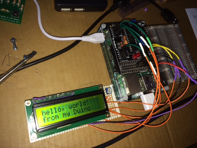

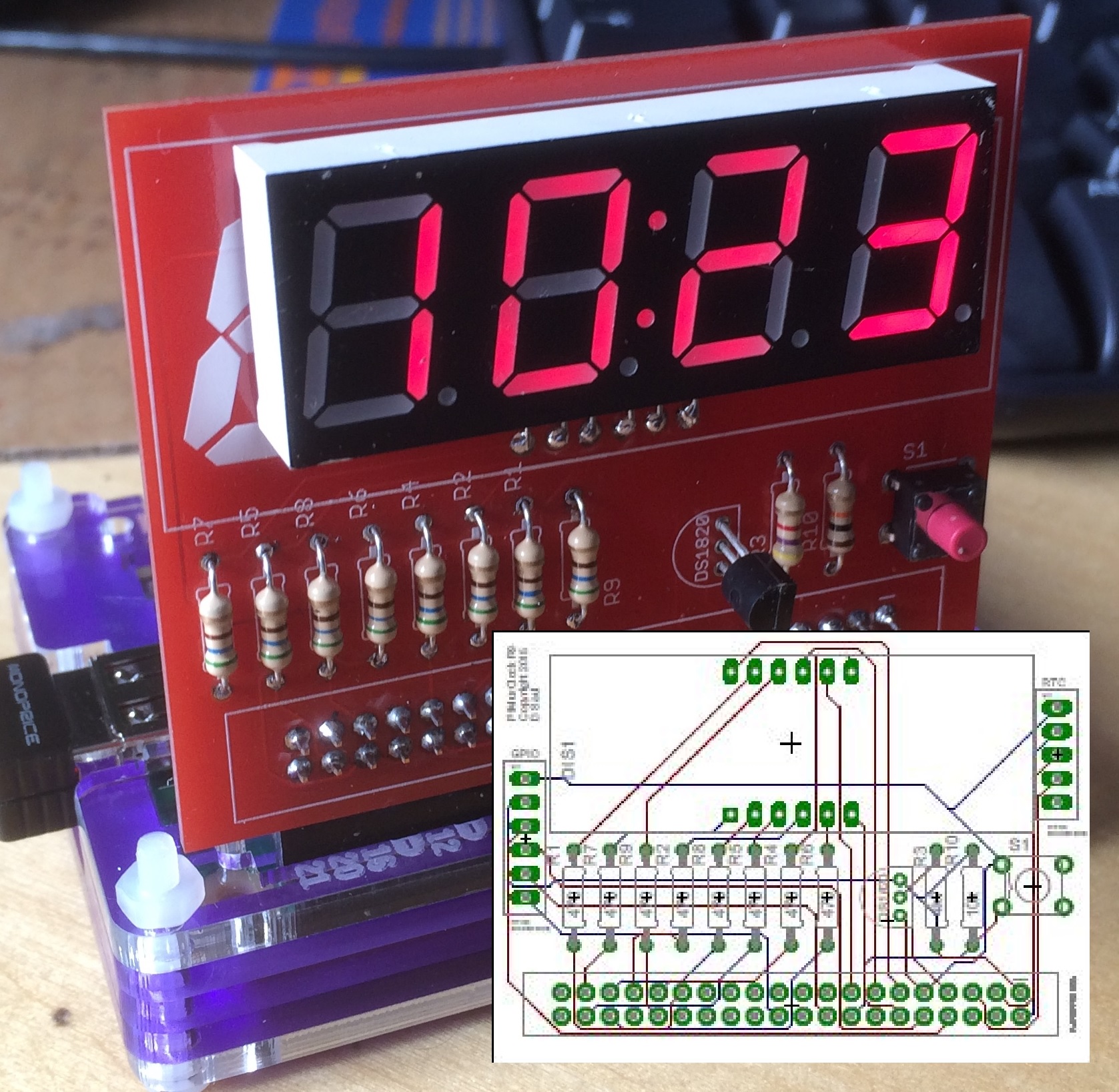
 allowing you to create a basic digital clock and temperature display for your RPi.


 od
od The software is build on some simple Python code adapted from various other projects using the Picamera library.